
Motor controller
Friday, 28 October 2011


Sunday, 26 June 2011
Heatbed heaters... using hair straightners
Well, since march, i been loking at making my own heat bed for my huxley.
Speaking online last night to reprappers on irc, i came up with the idea of using PTC heaters as a heating element for the heatbed. I saw these: which are available in 30v (powered from 12v) and 200watt versions.
Researching into these, it turns out that PTC heaters are used in Hair straightners too!
I looked in my local shop and the cheapest was £4.99 but these were not variable heating, these were £20 onwards. The veariable ones would be required, as these can go down as low as 40degrees C.
I decieded to try and get some second hand ones as the cost for a new one, that i could potentially break, as a bit outweighted.
The local Carboot sale prooved fruitfull. The 50p box at one stall revealed many electrical items including 4 sets of variable hair straightners.
The models i got are:
Remmington S-8200 (85 Watts)
Superdrugs own brand MCS3701/405965 (160 Watts)
KODO (cheap n nasty) KO300V (65 Watts)
Tony and Guy TG094 (Straightner adapter) (24-70Watts)
The first 2 are aluminium plates and the other 2 are ceramics.
The Tony and guy model features an LCD display!
All are variable and low on one model shows 60 degrees celcius! prfect for PLA
There are a few features that are a bit annoying... all have 60minute auto off! this should be bipassed by using a relay connected to the on/off switch and controlled through the mosfet on the electronics board. These are all 240 volt models and therefore could be VERY dangerous! Im using a RCD device when testing these, and hopefully i will still be living enough to finish this post :D
The KODO model
These by far look the cheapest, and the connector for the mains plug feels a bit gritty, so i will take these apart first f all.
The heaters which seem to be in heair straightners are PTC which is 'Positive
Temperature Coefficient' information can be found in more detail via http://www.dbk-usa.com/ptc-heaters
"Positive Temperature Coefficient (PTC) heating elements are small ceramic stones with self-limiting temperature characteristics. PTC stones have fast heating response times and plateau once the pre-defined reference temperature is reached. It is possible to form the stones into a square, rectangular, circular or ring shape. Above the reference temperature, the semiconducting and ferro-electrical properties of the ceramic are utilized to produce a rise in resistance of several orders of magnitude, and thereby creating it's self-limiting properties"
from
So, peltier stones ay? lets see what these look like...
Taking apart the KODO heater, it is obvious why cheap hair straightners break, the wires are thin!
The circuit board seems to feature AC input into a TRIAC http://www.datasheetcatalog.org/datasheet/stmicroelectronics/8666.pdf BTB04-600SL The heater wires connect to one power side, then then the TRIAC.
The temperature wires - i assume a thermistor like we use on repraps, connects to power and a small chip, PM3/8U? which i assume is a microcontroller.
The heater elements look as if it is clamped into the ceramic housing, this is to force contact onto the ceramic plate.
The heating element is actually loose and taped together using polyimide tape but features 2 power plates and 2 ceramic Peltier? blocks, all sandwiched together.
The fact these are loose means that this is a very cheaply made unit, and the ones on farnell seem to be housed inside an alumninium block.
Eitherway, if i were to use these i will have to force contact.
The remington straightners.
These are aluminium plates and could be very easy to bolt to an aluminium plate.
Again a small circuit board, with a TRIAC and variable resistor.
The aluminium plates also seem to have loose PTC elements (this time taped togeter in more kapton tape, but a much larger plate!
The superdrug straightners.
OOh a nice WADE spring!
Again, the heating plate is made up of 2 plates and some ceramic plates inside,
but this time the plates are mecahincally clamped in
Speaking online last night to reprappers on irc, i came up with the idea of using PTC heaters as a heating element for the heatbed. I saw these: which are available in 30v (powered from 12v) and 200watt versions.
Researching into these, it turns out that PTC heaters are used in Hair straightners too!
I looked in my local shop and the cheapest was £4.99 but these were not variable heating, these were £20 onwards. The veariable ones would be required, as these can go down as low as 40degrees C.
I decieded to try and get some second hand ones as the cost for a new one, that i could potentially break, as a bit outweighted.
The local Carboot sale prooved fruitfull. The 50p box at one stall revealed many electrical items including 4 sets of variable hair straightners.
The models i got are:
Remmington S-8200 (85 Watts)
Superdrugs own brand MCS3701/405965 (160 Watts)
KODO (cheap n nasty) KO300V (65 Watts)
Tony and Guy TG094 (Straightner adapter) (24-70Watts)
The first 2 are aluminium plates and the other 2 are ceramics.
The Tony and guy model features an LCD display!
All are variable and low on one model shows 60 degrees celcius! prfect for PLA
There are a few features that are a bit annoying... all have 60minute auto off! this should be bipassed by using a relay connected to the on/off switch and controlled through the mosfet on the electronics board. These are all 240 volt models and therefore could be VERY dangerous! Im using a RCD device when testing these, and hopefully i will still be living enough to finish this post :D
The KODO model
These by far look the cheapest, and the connector for the mains plug feels a bit gritty, so i will take these apart first f all.
The heaters which seem to be in heair straightners are PTC which is 'Positive
Temperature Coefficient' information can be found in more detail via http://www.dbk-usa.com/ptc-heaters
"Positive Temperature Coefficient (PTC) heating elements are small ceramic stones with self-limiting temperature characteristics. PTC stones have fast heating response times and plateau once the pre-defined reference temperature is reached. It is possible to form the stones into a square, rectangular, circular or ring shape. Above the reference temperature, the semiconducting and ferro-electrical properties of the ceramic are utilized to produce a rise in resistance of several orders of magnitude, and thereby creating it's self-limiting properties"
from
So, peltier stones ay? lets see what these look like...
Taking apart the KODO heater, it is obvious why cheap hair straightners break, the wires are thin!
The circuit board seems to feature AC input into a TRIAC http://www.datasheetcatalog.org/datasheet/stmicroelectronics/8666.pdf BTB04-600SL The heater wires connect to one power side, then then the TRIAC.
The temperature wires - i assume a thermistor like we use on repraps, connects to power and a small chip, PM3/8U? which i assume is a microcontroller.
The heater elements look as if it is clamped into the ceramic housing, this is to force contact onto the ceramic plate.
The heating element is actually loose and taped together using polyimide tape but features 2 power plates and 2 ceramic Peltier? blocks, all sandwiched together.
The fact these are loose means that this is a very cheaply made unit, and the ones on farnell seem to be housed inside an alumninium block.
Eitherway, if i were to use these i will have to force contact.
The remington straightners.
These are aluminium plates and could be very easy to bolt to an aluminium plate.
Again a small circuit board, with a TRIAC and variable resistor.
The aluminium plates also seem to have loose PTC elements (this time taped togeter in more kapton tape, but a much larger plate!
The superdrug straightners.
OOh a nice WADE spring!
Again, the heating plate is made up of 2 plates and some ceramic plates inside,
but this time the plates are mecahincally clamped in
Its been a while... - update for past 4 months
Hi folks, whats new?
Well its been a few months since my last post, and i been needing to update things.
Basically i am creating the Huxley MD (My Design) reprap machine with my machine, and also started to make a stepper struder for my makerbot - running mk5!
so there has been lots to talk about.
After heading to the makerfaire in nottingham, i spoke to jeanmarc of emaker shop, and saw the small huxley he was making, i liked it, and wanted to make it. I didnt like the design for the extruder, and i wanted a more recognisable extruder that has been used, therefore i wanted to use the makergear hot end.
Also i wanted to use different bearings, lm6uu for 6mm rods.
I designed the parts and a picture will be put here, but there are flickr pictures!
I also have bought some angel eyes from ebay to fit onto my makerbot and reprap - 90mm and 50mm diameter lights! VERY nice and a recommendation to all!
The makerbot has been upgraded to feature a stepper motor, and im waiting for the gen 4 stepper motorfrom makerbot to fit onto it and make it amazing :)
Looking at stewarts build, the stepper motor design makes FAR better quality prints!
anyways, im also trying to design a heat bed for the huxley 140mm by 140mm so that Jeanmarc can use them on his emakers he is selling, and i can have one for myself!
sadly the etch tank has become too full of copper, and therefore i need to dispose of it and start with a fresh ammount of acid. This is a complex process involving taking the chemical to a hazardous waste recycling facility! and costs!
anyways, thats a brief summary of whats been going on. Oh and i got woodworm in my room, so im hoping its not going to the makerbot!!!
Well its been a few months since my last post, and i been needing to update things.
Basically i am creating the Huxley MD (My Design) reprap machine with my machine, and also started to make a stepper struder for my makerbot - running mk5!
so there has been lots to talk about.
After heading to the makerfaire in nottingham, i spoke to jeanmarc of emaker shop, and saw the small huxley he was making, i liked it, and wanted to make it. I didnt like the design for the extruder, and i wanted a more recognisable extruder that has been used, therefore i wanted to use the makergear hot end.
Also i wanted to use different bearings, lm6uu for 6mm rods.
I designed the parts and a picture will be put here, but there are flickr pictures!
I also have bought some angel eyes from ebay to fit onto my makerbot and reprap - 90mm and 50mm diameter lights! VERY nice and a recommendation to all!
The makerbot has been upgraded to feature a stepper motor, and im waiting for the gen 4 stepper motorfrom makerbot to fit onto it and make it amazing :)
Looking at stewarts build, the stepper motor design makes FAR better quality prints!
anyways, im also trying to design a heat bed for the huxley 140mm by 140mm so that Jeanmarc can use them on his emakers he is selling, and i can have one for myself!
sadly the etch tank has become too full of copper, and therefore i need to dispose of it and start with a fresh ammount of acid. This is a complex process involving taking the chemical to a hazardous waste recycling facility! and costs!
anyways, thats a brief summary of whats been going on. Oh and i got woodworm in my room, so im hoping its not going to the makerbot!!!
Well, its been a while
Hi folks, whats new?
Well its been a few months since my last post, and i been needing to update things.
Basically i am creating the Huxley MD (My Design) reprap machine with my machine, and also started to make a stepper struder for my makerbot - running mk5!
so there has been lots to talk about.
After heading to the makerfaire in nottingham, i spoke to jeanmarc of emaker shop, and saw the small huxley he was making, i liked it, and wanted to make it. I didnt like the design for the extruder, and i wanted a more recognisable extruder that has been used, therefore i wanted to use the makergear hot end.
Also i wanted to use different bearings, lm6uu for 6mm rods.
I designed the parts and a picture will be put here, but there are flickr pictures!
I also have bought some angel eyes from ebay to fit onto my makerbot and reprap - 90mm and 50mm diameter lights! VERY nice and a recommendation to all!
The makerbot has been upgraded to feature a stepper motor, and im waiting for the gen 4 stepper motorfrom makerbot to fit onto it and make it amazing :)
Looking at stewarts build, the stepper motor design makes FAR better quality prints!
anyways, im also trying to design a heat bed for the huxley 140mm by 140mm so that Jeanmarc can use them on his emakers he is selling, and i can have one for myself!
sadly the etch tank has become too full of copper, and therefore i need to dispose of it and start with a fresh ammount of acid. This is a complex process involving taking the chemical to a hazardous waste recycling facility! and costs!
anyways, thats a brief summary of whats been going on. Oh and i got woodworm in my room, so im hoping its not going to the makerbot!!!
Well its been a few months since my last post, and i been needing to update things.
Basically i am creating the Huxley MD (My Design) reprap machine with my machine, and also started to make a stepper struder for my makerbot - running mk5!
so there has been lots to talk about.
After heading to the makerfaire in nottingham, i spoke to jeanmarc of emaker shop, and saw the small huxley he was making, i liked it, and wanted to make it. I didnt like the design for the extruder, and i wanted a more recognisable extruder that has been used, therefore i wanted to use the makergear hot end.
Also i wanted to use different bearings, lm6uu for 6mm rods.
I designed the parts and a picture will be put here, but there are flickr pictures!
I also have bought some angel eyes from ebay to fit onto my makerbot and reprap - 90mm and 50mm diameter lights! VERY nice and a recommendation to all!
The makerbot has been upgraded to feature a stepper motor, and im waiting for the gen 4 stepper motorfrom makerbot to fit onto it and make it amazing :)
Looking at stewarts build, the stepper motor design makes FAR better quality prints!
anyways, im also trying to design a heat bed for the huxley 140mm by 140mm so that Jeanmarc can use them on his emakers he is selling, and i can have one for myself!
sadly the etch tank has become too full of copper, and therefore i need to dispose of it and start with a fresh ammount of acid. This is a complex process involving taking the chemical to a hazardous waste recycling facility! and costs!
anyways, thats a brief summary of whats been going on. Oh and i got woodworm in my room, so im hoping its not going to the makerbot!!!
Saturday, 12 March 2011
regarding poaterobotics.co.cc - business card web address issue :(
After handing out many business card at Makerfaire UK 2011, it has become apparent that my registration for co.cc has expired as of 4 days ago.
Sadly i cannt log into my account and therefore people looking for it, it will not display.
If you are one of those people, please visit the original hosting address of:
http://www.poaterobotics.webs.com
this is currently being updated so please take a look and contact me for any info.
Sadly i cannt log into my account and therefore people looking for it, it will not display.
If you are one of those people, please visit the original hosting address of:
http://www.poaterobotics.webs.com
this is currently being updated so please take a look and contact me for any info.
Friday, 12 November 2010
yay! dont you just love payday!
well, pay day is upon us, well its been a few days and aftre sorting out all my other bits ni need to buy, i decieded to put money towards a mk5 and a few other bit and pieces for the makerbot... so putting in my order, i am dreading the cost of uk import tax... estimate it to be about £50 so when it comes i will let you know, but... it has been ordered!
for some reason i cant add a pic... but the total cost was $259.70, thats about £158.
i got:
mk5 plastruder full kit: $185 (£114.42)
2 x lengths of nichrome to replace mk4 bits: $10 (£6.18)
frostruder mk2 experimenters kit - to use on my pcb smt setup: $20 (£12.37)
10 x 3mm gold magnets: $2.50 (£1.54)
and postage: $42.20 (£26.10)
we shall see! its been shipped along with some timing belts to replace the ones i have originally, they were open ended belts glued together with wet suit glue so will eventully break!
but yay,
need to also buy a new stepper motor chip...
for some reason i cant add a pic... but the total cost was $259.70, thats about £158.
i got:
mk5 plastruder full kit: $185 (£114.42)
2 x lengths of nichrome to replace mk4 bits: $10 (£6.18)
frostruder mk2 experimenters kit - to use on my pcb smt setup: $20 (£12.37)
10 x 3mm gold magnets: $2.50 (£1.54)
and postage: $42.20 (£26.10)
we shall see! its been shipped along with some timing belts to replace the ones i have originally, they were open ended belts glued together with wet suit glue so will eventully break!
but yay,
need to also buy a new stepper motor chip...
Friday, 22 October 2010
Blue magic smoke :(
So, here it is... as im designing a shell for use in a project, which needs to be completed by Wednesday... for the MCM expo! Yes the MCM expo in london next weekend, i go to use my makerbot, and sadly the Z axis starts playing up... then a wiff, snap crackle and pop (and no mini cartoon characters to see for miles) the stepper motor controller decieds to frazzle.
Luckily when the first time this happened, i ordered 2 spare chips, so i can replace the chip, will just take time...
Here goes!
Luckily when the first time this happened, i ordered 2 spare chips, so i can replace the chip, will just take time...
Here goes!
Wednesday, 20 October 2010
Building of wobble arrester and new cable
Well its been an eventfull couple of weeks.
firtly i decieded to change my usb ttl adapter for the makerbot to a 5v logic level, as apposed tothe 3.3v logic level one i was using. the idea behind this was that the switchover signal voltage could have been too low and therefore meant the data was not being sent at good quality. I was annoyed when i bought the first cable, as i was thinking it was a 5v level cable, but alas... oh well.
the first tests came as i was setting up the uni makerbot for a demo of high calibre... more on that in a sec, but i managed to start repg and the new software version, meaning i could import and manipulate the files stl etc in repg.
the first trial pieces were done using my pc desktop, an old pentium 4. (i now bought a i5 HP laptop, so yay!) I did wounder if the processing speed was too slow for the makerbot, and i think i might have been right...
anyway, my first prints using the 5v cable, turned out to be good. they were a corner bracket, to try simple shapes... and then the z wobble arrester. this is an amazing thing an im glad i printed it, as my sides are virtually wobble free (need a second one for other side of rear as that too is a bit wobbly...
anyhow, i printed these with great success, installed the wob arr and set to print something more complex. The gear set, recently uploaded seemd lie the perfetc vhoice.
link here :(insert link)
the results seemed ok, but the thinner smaller gear had to be height adjusted as too much plastic was comming out causing lumps. - this maybe because there wasnt enough time to cool befre the heater nozel came ploughing through, so need to work on 'cool' settings as mentioned in recent blog post elsewhere - should really write the links down!. need to adjust speed and extruder flow rate too, both adjust this issue.
right a picture...
or 2...
the L bracket, shows several wobbly edges so off to print the z wobble arrester...
the wobble arrested whilst printing
The wobble arrester works wonders, and if anyone needs to see why it is handy, check this video out of the one i installed...
with the wobble arrester installed, i made the gears.
picture too come.
firtly i decieded to change my usb ttl adapter for the makerbot to a 5v logic level, as apposed tothe 3.3v logic level one i was using. the idea behind this was that the switchover signal voltage could have been too low and therefore meant the data was not being sent at good quality. I was annoyed when i bought the first cable, as i was thinking it was a 5v level cable, but alas... oh well.
the first tests came as i was setting up the uni makerbot for a demo of high calibre... more on that in a sec, but i managed to start repg and the new software version, meaning i could import and manipulate the files stl etc in repg.
the first trial pieces were done using my pc desktop, an old pentium 4. (i now bought a i5 HP laptop, so yay!) I did wounder if the processing speed was too slow for the makerbot, and i think i might have been right...
anyway, my first prints using the 5v cable, turned out to be good. they were a corner bracket, to try simple shapes... and then the z wobble arrester. this is an amazing thing an im glad i printed it, as my sides are virtually wobble free (need a second one for other side of rear as that too is a bit wobbly...
anyhow, i printed these with great success, installed the wob arr and set to print something more complex. The gear set, recently uploaded seemd lie the perfetc vhoice.
link here :(insert link)
the results seemed ok, but the thinner smaller gear had to be height adjusted as too much plastic was comming out causing lumps. - this maybe because there wasnt enough time to cool befre the heater nozel came ploughing through, so need to work on 'cool' settings as mentioned in recent blog post elsewhere - should really write the links down!. need to adjust speed and extruder flow rate too, both adjust this issue.
right a picture...
or 2...
the L bracket, shows several wobbly edges so off to print the z wobble arrester...
the wobble arrested whilst printing
The wobble arrester works wonders, and if anyone needs to see why it is handy, check this video out of the one i installed...
with the wobble arrester installed, i made the gears.
picture too come.
Sunday, 10 October 2010
dead...
mkerbot mk4 plastruder is dead. and i dont have money to buy the mk5. uni have bought the last of my nichrome wire so i dont have the ability to rectify, therefore i have decieded to stick it in the loft and forget about it till i have money.
Monday, 27 September 2010
Release of Thing-o-matic

no relation to wallace and gromit, but makerbot have now released the next gen of makerbot! the thing-o-matic provides automatic printing with the belted buikld base and much finer resolution printing!
It is a shame the cost hasd also increased! sadly to import one of these into the UK, will cost £711 for the kit, postage about £30? then charges totalling an estimated £140, making the total cost £900... sadly i cannot afford this, but am very tempted to break open the uni laser cutter and make myself one when the files become available :D
all for now, but check out the details online:
Sunday, 22 August 2010
Solidwork developments

abves y firt trialseeeeeebly wiiiiiiiiiiasme art desghned in solorksTHIWI CME Y EBAL MSCH FORRYYNIAAICCF
and now with new batteries in my keyboard...
Above is my first trial assembly which contasins several parts i designed in solidworks. This will form the eye mech for my animatronic head.
Thursday, 29 July 2010
Animatronic Skin and Teeth
I recently bought some Platsil Gel10 to make robotic skin from www.dauphines.co.uk they did a good price, and also sell plastic human eyes aswell - something cheap and chearfull that i could use on my larger heads.
I bought 2kg tubs of the stuff, as well as skin pigment for the silicone. that and 2 eyes came to £61.20 plus £7 postage.
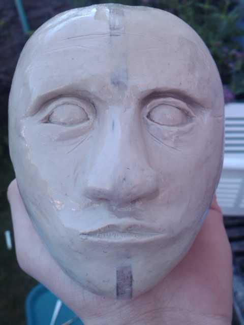
The sculpture i made was of a human head whichj is about 11-12 cm tall

here you can see the small ears i made - these are about 3cm tall.
I started off with 2 inmages from google - a portrait and a side view of a male, i resized both to the same size and then used these to cut out a wooden template. The clay was then sculpted around these 2 pieces to form the smape of the head.

this is a close-up of one of the ears. I am pleased ith this one. I didnt use any references but just feeling my own ears.
Sadly, copying this ear pattern to the other side was more difficult than I thought it would be.
This is the final head with its acrylic coating. I should have spent more time smoothing it down, but this being my first project to hopefully a good portfolio, i wanted to just get it done and see what it looked like.
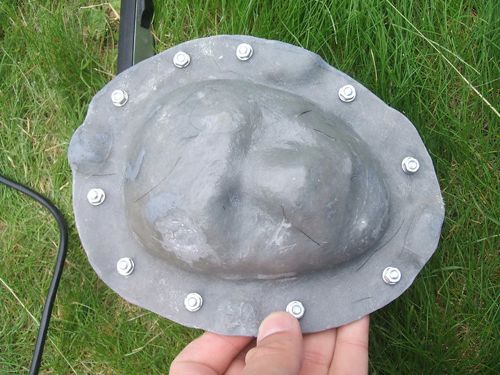
i then made a mould of the glay head using fibreglass matt and sheet - using gelcoat (sadly not witht he catalyst) and built a 3 segmented mould


The next step was to make the eyes, for this i used 15cm wooden beads which i bought from the local bead-ery shop (lol)
I cut them just past half way, and hollowed out the insides of them, allowing me to fit in a ball joint (will need to change this as it allows full movem,ent not just movement in x and y.)

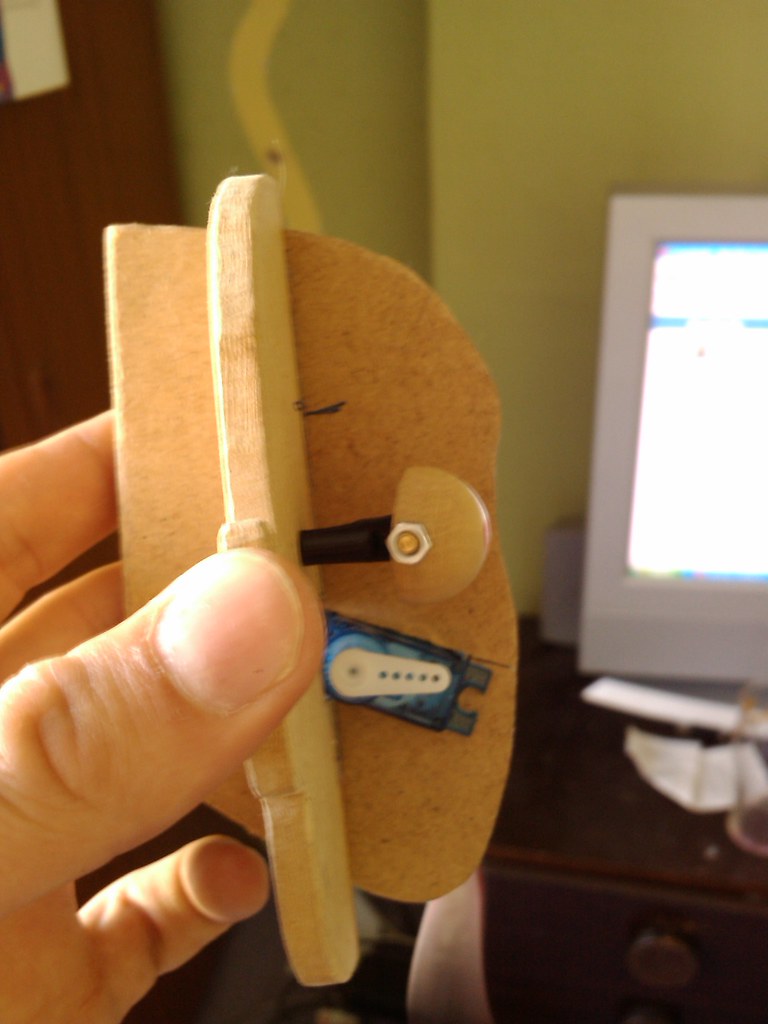
The servo will be mounted behind the eyes, and this is an ongoing task. - the servo seen in the picture is for the jaw.
The wooden shapes are taken from the ear-to-ear template i made for the sculpture.
The front to back piece was cut out using the rear of the mould used for the skin. This means that there is a small gap between the skin and this piece - to be made from aluminium at a later date.


This is the outer skin, it is made by layering thin clay into the negative fibreglass mould, then a layer of fibreglass is layed ontop of this.
As i did the face seperate from the rest of the head - due to my 3 part mould i made (it doesnt go over a head so i adopted a different method to Daniele Tirinnanzi )
The inner mould was made which overlapped the edge, which means i can refit the inner mould to the existing keys from the front so that it all lines up correctly.
[image to come]

The rear of the skin shows the thickness and the nose which i filled in with the silicone to create a smooth base to fit onto the metal chasis inside when i finished it.
Now onto the teeth:
I purchased some dental acrylic from dentala2z which is actually used to repair dentures (if you know of better supplies, please let me know.)
This method uses powdered acrylic And a liquid (similar to acetone but smells much more potent) which melts and bonds the acrylic particles together. This creates an acrylic liquid which is pourable into the moulds.
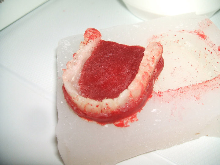
I started off with a lump of clay, about 5mm thick, then added a bead of clay around the edge to form the teeth. The teeth were sculpted roughly – again this was my first attempt so I wanted a result, but these were actually good enough anyway. The gum lines were then sculpted into the base layer, and a silicone mould was made using platsil Gel10 (I ran out of standard silicone)
Pouring the acrylic liquid into the mould made castings of the teeth. I did this twice, then using a dremil I cut away the gum part of the casting to reveal just the white teeth.
Using food colouring, I made some more acrylic liquid and turned it red.
I placed the teeth into the mould, using a bit of petroleum jelly to seal the teeth and to stop the red acrylic sticking to parts of the teeth, I poured in the red solution.

The red gum part is a bit dark, and it also spilled onto the teeth, but because of the petroleum jelly, this was easily cleaned off - tho some staining had occoured. Next time i will be using special gum coloured dental acrylic, sadly i thought i bought white and red coloured stuff, but i hadnt. I will not be using food colouring again and i dont really recomend it!
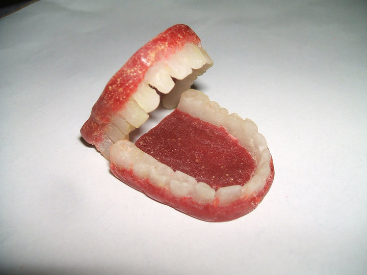
The final teeth:

The teeth inside the skin (stretched over my hand)

So there we go, this is where i have got too.
thank you :)
nat :D
I bought 2kg tubs of the stuff, as well as skin pigment for the silicone. that and 2 eyes came to £61.20 plus £7 postage.
The sculpture i made was of a human head whichj is about 11-12 cm tall

here you can see the small ears i made - these are about 3cm tall.
I started off with 2 inmages from google - a portrait and a side view of a male, i resized both to the same size and then used these to cut out a wooden template. The clay was then sculpted around these 2 pieces to form the smape of the head.
this is a close-up of one of the ears. I am pleased ith this one. I didnt use any references but just feeling my own ears.
Sadly, copying this ear pattern to the other side was more difficult than I thought it would be.
This is the final head with its acrylic coating. I should have spent more time smoothing it down, but this being my first project to hopefully a good portfolio, i wanted to just get it done and see what it looked like.
i then made a mould of the glay head using fibreglass matt and sheet - using gelcoat (sadly not witht he catalyst) and built a 3 segmented mould


The next step was to make the eyes, for this i used 15cm wooden beads which i bought from the local bead-ery shop (lol)
I cut them just past half way, and hollowed out the insides of them, allowing me to fit in a ball joint (will need to change this as it allows full movem,ent not just movement in x and y.)

The servo will be mounted behind the eyes, and this is an ongoing task. - the servo seen in the picture is for the jaw.
The wooden shapes are taken from the ear-to-ear template i made for the sculpture.
The front to back piece was cut out using the rear of the mould used for the skin. This means that there is a small gap between the skin and this piece - to be made from aluminium at a later date.

This is the outer skin, it is made by layering thin clay into the negative fibreglass mould, then a layer of fibreglass is layed ontop of this.
As i did the face seperate from the rest of the head - due to my 3 part mould i made (it doesnt go over a head so i adopted a different method to Daniele Tirinnanzi )
The inner mould was made which overlapped the edge, which means i can refit the inner mould to the existing keys from the front so that it all lines up correctly.
[image to come]
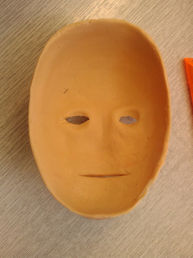
The rear of the skin shows the thickness and the nose which i filled in with the silicone to create a smooth base to fit onto the metal chasis inside when i finished it.
Now onto the teeth:
I purchased some dental acrylic from dentala2z which is actually used to repair dentures (if you know of better supplies, please let me know.)
This method uses powdered acrylic And a liquid (similar to acetone but smells much more potent) which melts and bonds the acrylic particles together. This creates an acrylic liquid which is pourable into the moulds.
I started off with a lump of clay, about 5mm thick, then added a bead of clay around the edge to form the teeth. The teeth were sculpted roughly – again this was my first attempt so I wanted a result, but these were actually good enough anyway. The gum lines were then sculpted into the base layer, and a silicone mould was made using platsil Gel10 (I ran out of standard silicone)
Pouring the acrylic liquid into the mould made castings of the teeth. I did this twice, then using a dremil I cut away the gum part of the casting to reveal just the white teeth.
Using food colouring, I made some more acrylic liquid and turned it red.
I placed the teeth into the mould, using a bit of petroleum jelly to seal the teeth and to stop the red acrylic sticking to parts of the teeth, I poured in the red solution.
The red gum part is a bit dark, and it also spilled onto the teeth, but because of the petroleum jelly, this was easily cleaned off - tho some staining had occoured. Next time i will be using special gum coloured dental acrylic, sadly i thought i bought white and red coloured stuff, but i hadnt. I will not be using food colouring again and i dont really recomend it!
The final teeth:
The teeth inside the skin (stretched over my hand)

So there we go, this is where i have got too.
thank you :)
nat :D
Saturday, 12 June 2010
fibre glass
i went to see my technician friend at uni, and managed to aquire a load of fiberglass stuff...
glass matt (stranded stuff - bout the weaved matt from ebay)
PVA release agent
Honey wax release agent
resin and catalyis
gelcoat
so later today, my friend Caz will be comming over to assist me with some fun fiberglassing!
Yay!!!
glass matt (stranded stuff - bout the weaved matt from ebay)
PVA release agent
Honey wax release agent
resin and catalyis
gelcoat
so later today, my friend Caz will be comming over to assist me with some fun fiberglassing!
Yay!!!
Monday, 10 May 2010
Aluminium!!!
Just been to the tech stores and managed to aquire some sheet aluminium and angle bar, rods for making my very own animatronic (im going to last longer than lego) head mech!
This will form part of my animatronic mask and eye/tail mech which i will cover in latex/silicone cover moulded from oil based clay!
Cant wait!
This will form part of my animatronic mask and eye/tail mech which i will cover in latex/silicone cover moulded from oil based clay!
Cant wait!
Wednesday, 5 May 2010
mk4 plastruder mod for those with issues??!!?!
javascript:void(0)
Well, actually i think i have pioneered a new mod for the plastruder!
After about a month of unsuccessful prints with my faulty plastruder, i finally took my dremel tool to it and modded it!
The issue i was having was that the idler wheel would let the filament slip sideways off of the edge, sitting nicely in the corner and failing to budge causing a faulty print.
One of the issues that originally caused this was that the 'lid' to my timing pulley which fits onto the plastruder motor came off - it fell off after about 3 days - and that was many months ago before makerbot 100 was shipped!
i needed something to stop the filament sliding off to the side and getting into the corner.
The pulley placed on the end of the motor shaft did stop this, but eventually the force of the filament trying to escape the jaws of the pulley teeth would push the bearing out. i needed a way to fix it so that this force could not push on the outside and free itself.
My idea....
well. as i originally said, my plastruder timing belt lid had come off... my idea was to dremel the rough end of the timing pulley (so the teeth were flush to the end) rotate it round, and instead of having the bearing on last, was to swap it round. The bearing would fit first onto the motor shaft, then the pulley - but rotated so the screw threads would tighten furthest away from the motor. The idea being, as the motor would force the filament down, it could not pus to the side as it would push against the thicker part of the timing pulley - which is fixed...... lest see a picture!

here is the old setup, the end of the timing pulley had come away.

The pulley is placed on first, then the timing pulley - note i have tidied the end of the timing pulley to provide a flush flat edge - see previous photo)

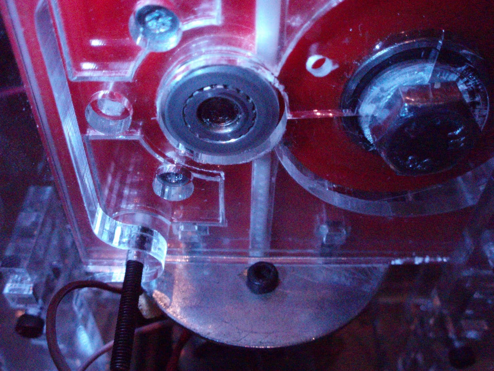
In situe in the plastruder casing, the pulley and bearing fit perfectly and line up with the filament guides.

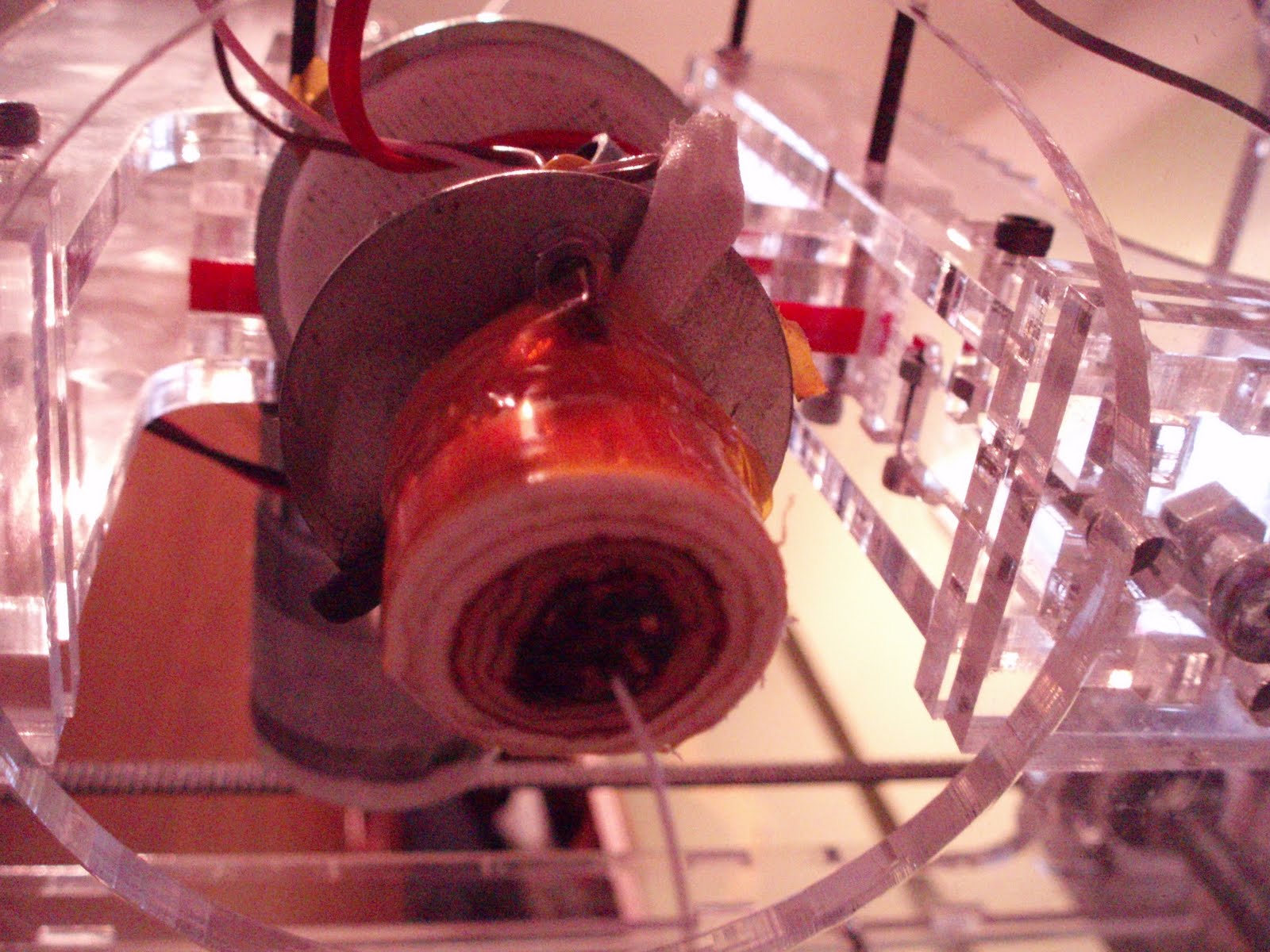
the filament is fed nicely through to the heater barrel.

hurray! filament is feeding at a great rate - motor set at 255 and no stripping of threads!
Also another mod i have added... A fan connected to the fan connector on the extruder mobo is positioned over the mosfets to keep the cooler - i will make some heatsinks but this seems alright so far!
Sadly they can be turned on/off using the fan control box on the control panel, however using the 'cool' function set in skeinforge (with values set to 0 and fan on at startup) we are able to make the software turn on the fan and leave it on for the entirety of the print and on afterward as well!

I must also add that the temperature of my heater barrel dropped always to 220, which caused some of the failed prints. i only just realised that this is a setting specified in the startup code. i have now modified this to display 240, and to remain hot at the end by modding the end.gcode file!
I have now had a successful continuous feed of abs t full pwm (255) for 10 minutes!
Maybe i can finally get to use my 12Kg coil of Black ABS!
Well, actually i think i have pioneered a new mod for the plastruder!
After about a month of unsuccessful prints with my faulty plastruder, i finally took my dremel tool to it and modded it!
The issue i was having was that the idler wheel would let the filament slip sideways off of the edge, sitting nicely in the corner and failing to budge causing a faulty print.
One of the issues that originally caused this was that the 'lid' to my timing pulley which fits onto the plastruder motor came off - it fell off after about 3 days - and that was many months ago before makerbot 100 was shipped!
i needed something to stop the filament sliding off to the side and getting into the corner.
The pulley placed on the end of the motor shaft did stop this, but eventually the force of the filament trying to escape the jaws of the pulley teeth would push the bearing out. i needed a way to fix it so that this force could not push on the outside and free itself.
My idea....
well. as i originally said, my plastruder timing belt lid had come off... my idea was to dremel the rough end of the timing pulley (so the teeth were flush to the end) rotate it round, and instead of having the bearing on last, was to swap it round. The bearing would fit first onto the motor shaft, then the pulley - but rotated so the screw threads would tighten furthest away from the motor. The idea being, as the motor would force the filament down, it could not pus to the side as it would push against the thicker part of the timing pulley - which is fixed...... lest see a picture!

here is the old setup, the end of the timing pulley had come away.

The pulley is placed on first, then the timing pulley - note i have tidied the end of the timing pulley to provide a flush flat edge - see previous photo)

In situe in the plastruder casing, the pulley and bearing fit perfectly and line up with the filament guides.
the filament is fed nicely through to the heater barrel.
hurray! filament is feeding at a great rate - motor set at 255 and no stripping of threads!
Also another mod i have added... A fan connected to the fan connector on the extruder mobo is positioned over the mosfets to keep the cooler - i will make some heatsinks but this seems alright so far!
Sadly they can be turned on/off using the fan control box on the control panel, however using the 'cool' function set in skeinforge (with values set to 0 and fan on at startup) we are able to make the software turn on the fan and leave it on for the entirety of the print and on afterward as well!

I must also add that the temperature of my heater barrel dropped always to 220, which caused some of the failed prints. i only just realised that this is a setting specified in the startup code. i have now modified this to display 240, and to remain hot at the end by modding the end.gcode file!
I have now had a successful continuous feed of abs t full pwm (255) for 10 minutes!
Maybe i can finally get to use my 12Kg coil of Black ABS!
Wednesday, 28 April 2010
my mini head can see clearly now (with clear perspex shell)
After a few weeks i recieved my new makerbot shell from uni, sadly during constructions, 2 pieces went snap, therefore i have an almost clear makerbot shell... - pics in my flickr pool!
this evening, i finally managed to get the motors soldered into place and test the thing out. The lights from the electronics illuminates the makerbot industries engraving rather nicely!
also downloaded the new ReplicatorG and tested out the new preference settings - my heated build base was not getting to the correct temp as i was using a 1mm thermistor and the 3mm settings - the extruder had a 3mm thermistor.
so i finally tested it extruding, and wow... heats up, looks very sweet and .... ah... sadly the filament stripped. need to move the idler wheel closer!
other than that, i bought a few more 5gram servos to make a small miniture animatronic head. Im designing it using sketchpad and consists of a jaw, square skull with curved pieces, eyes that move left right uop and down, and eventually eye lids - all printable on the makerbot. here is for good testing tomorrow!
over and out tonight.
Nat
this evening, i finally managed to get the motors soldered into place and test the thing out. The lights from the electronics illuminates the makerbot industries engraving rather nicely!
also downloaded the new ReplicatorG and tested out the new preference settings - my heated build base was not getting to the correct temp as i was using a 1mm thermistor and the 3mm settings - the extruder had a 3mm thermistor.
so i finally tested it extruding, and wow... heats up, looks very sweet and .... ah... sadly the filament stripped. need to move the idler wheel closer!
other than that, i bought a few more 5gram servos to make a small miniture animatronic head. Im designing it using sketchpad and consists of a jaw, square skull with curved pieces, eyes that move left right uop and down, and eventually eye lids - all printable on the makerbot. here is for good testing tomorrow!
over and out tonight.
Nat
Friday, 16 April 2010
Rats... plastic tears and wooden saviours
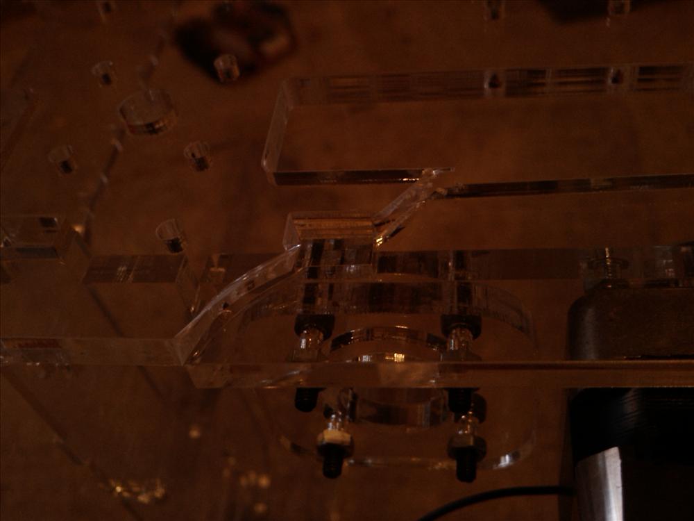
Last night I decided to take apart my makerbot and put it in its new shell properly.
Something’s I didn’t not take into consideration was the extra holes I made in the printer chamber base to attach the electronics, nor the fact I soldered the wires for the motor.
After cutting them, I continued to piece together the shell, sadly it didn’t quite fit resulting in the fragile plastic shell snapping in more than 3 places... as well as having the tabs snap off about 3 places.
I’m not enjoying it at all... so now I’m left with a makerbot shell snapped, a wooden shell, and a makerbots bits box that need rebuilding... fun... not.
The conclusion of the day - make the tabs bigger than the material so that it will slot in easily, or failing that...
DONT MAKE IT OUT OF PLASTIC! Wood is the way to go.

Something’s I didn’t not take into consideration was the extra holes I made in the printer chamber base to attach the electronics, nor the fact I soldered the wires for the motor.
After cutting them, I continued to piece together the shell, sadly it didn’t quite fit resulting in the fragile plastic shell snapping in more than 3 places... as well as having the tabs snap off about 3 places.
I’m not enjoying it at all... so now I’m left with a makerbot shell snapped, a wooden shell, and a makerbots bits box that need rebuilding... fun... not.
The conclusion of the day - make the tabs bigger than the material so that it will slot in easily, or failing that...
DONT MAKE IT OUT OF PLASTIC! Wood is the way to go.
Sunday, 11 April 2010
Black as night, Evil as Darthvader!
Afternoon on this glorious sunny day!
i thought i would start printing with my black ABS to see whgat it is like. and results are good!
Unfortunatly i have had a few flossing issues - but i will sort that out later.
The first thing i needed to do was to feed through the black abs. This would be odd as i have been using white ABS so it was interesting to see a fhite filament turn grey as it mixed with the black ABS.

The next thing to do ws to use my Darf Vader i had previously Skeinforged... sadly i had deleted it when i was sorting out my hard drive, thereofre i opened skeinforge and redid it. Sadly skeinforge seems to get stuck and freeze half way through the process, therefore i tried my already skeinforged piece - the clean whistle.
First results seem to be good except the raft came off the build base, therefore i had to abbort, but it looks good so far!

It was a good opportunity to see the 'pea' of the whistle up close...

Anyways i need to close down now as im going to Portsmouth for my dentist appointment tomorrow! NHS for ya! cant loose an NHS dentist! (Im currently in plymouth!)
i thought i would start printing with my black ABS to see whgat it is like. and results are good!
Unfortunatly i have had a few flossing issues - but i will sort that out later.
The first thing i needed to do was to feed through the black abs. This would be odd as i have been using white ABS so it was interesting to see a fhite filament turn grey as it mixed with the black ABS.

The next thing to do ws to use my Darf Vader i had previously Skeinforged... sadly i had deleted it when i was sorting out my hard drive, thereofre i opened skeinforge and redid it. Sadly skeinforge seems to get stuck and freeze half way through the process, therefore i tried my already skeinforged piece - the clean whistle.
First results seem to be good except the raft came off the build base, therefore i had to abbort, but it looks good so far!

It was a good opportunity to see the 'pea' of the whistle up close...

Anyways i need to close down now as im going to Portsmouth for my dentist appointment tomorrow! NHS for ya! cant loose an NHS dentist! (Im currently in plymouth!)
Friday, 9 April 2010
Inow you see it... now you dont

This is my new makerbot shell from uni - as part of there makerbot manufacturing they cut me a new clear shell and plastic x and y stages aswell :) looks very sweet!
Thursday, 8 April 2010
New toys

Today i recieved good presies
A nice 12lb coil of plastic filament in evil black
A new free makerbot shell from the spare materials from the University of Plymouth makerbot making.
I will soon transfer mu parts from my wooden case to the acrylic one just after i have got my job (interview tomorrow) and tidied everything up.
I will keep the pare bits of wood however as the acrylic may snap - a bit has already broken a tab :(
The arrival of the plastic filament will be tested tomorrow when i start to extrude some - i already have Darthvader awaiting!
Again! Thank you!
Subscribe to:
Posts (Atom)

